Tuesday, February 24, 2015

Hog it


24 April 2015

I am **way** behind on this blogging thing, which is a shame because I'm sure to leave out lots of build details.  My beloved Boston Bruins have alas left me an entire Spring clear of any cheering obligations.  Perhaps I can get one of the Bruins to put down their golf clubs and help me build the boat -- they've got plenty of free time.  

As you can see in the accompanying photos, I was working on planing the hog.  The power planer made a huge mess and a lot of noise.  Not my favorite tool.  If I didn't have a job I would do all this by hand -- good exercise.  To get a decent view and better control of the planer, I put some old stair treads on milk crates and made a platform that ran from stem to stern.  I wish I could say I got each curve just so, but the reality is that I got it pretty close and will be relying on the epoxy to fill the gaps.  I'm not convinced that more care and time spent would have resulted in any significant difference.  I'm just not that skilled and the multitude of intersecting planes and angles are tricky enough to keep my constantly guessing on how well things fit.  I'm sure it could be better, but I'm also sure it will be plenty strong enough and not to 'gappy'.  A huge fraction of the hog comes off.  If I were to do this again, I think I would cut the hog on my band saw before I put it on the boat. 


Another view of the hog.  I attached blocks to the form so that I could then employ my old steel C-clamps.  I bought a few buckets of these clamps in an estate sale.  I'm sure the old carpenter would be happy to seem them put to such good use.


Still another view.  You can see that the lines are not perfect.  I did fine tune after this.


I figured out a bit later in the build that my shop vac would plug right into the planar.  Shame on me for not figuring this out sooner.  I spent an entire afternoon after the hog planing incident cleaning up all the surfaces in the shop.  I don't think I'll ever get it all out of the shop.  You can see the fraction of wood planed off in the picture below.  


Plane

25 April 2015

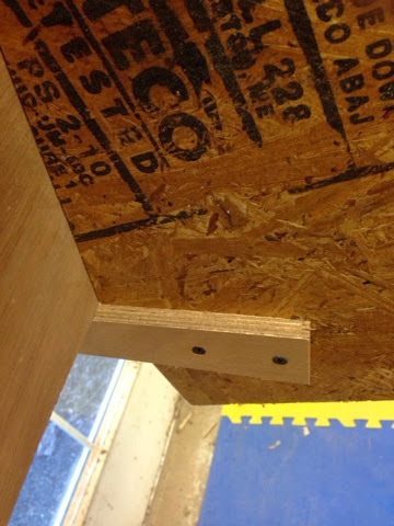
The photo below shows how I put the temporary screws holding the sides of the boat to chine too close to the edge.  I discovered this goof, too late, when I worked the angle of the chine in preparation for the bottom plywood.  Not the end of the world, but something to avoid.


In the photo below you can see the rough glue up where the side panel and chine meet the transom.   Lots of interesting angles to resolve here before the bottom sheathing goes on.


A phot showing the tolerance I accepted when a straight edge was laid down on the form.  There is a bit of a gap where I have taken a tad too much off the chine and side.  All these goofs will be underwater thankfully and out of sight from the Woods Hole boat building editorial staff.


Another view of the rough glue up looking from the transom forward.  Time to start planing this in prep for the bottom sheathing.


I have no idea why I took this picture of the bottom of the planer.  I think I was trying to convince myself that I had not destroyed the planer blades when I trimmed off some screw heads.


A photo showing the beginning of the line I established to accept the bottom sheathing.  You can see all the record-breaking snow I had outside.  You can also see one of my two little electric space heaters.  I managed to run up a $600 electric bill in one month.  That was unexpected and unfortunate since the room never got above 50.  I was essentially trying to melt all that snow.  Next year I will look into getting a propane heater installed.  I like this shot too because you get a sense of the line that Doug Hylan has established in the hull.

Sunday, February 8, 2015

Attaching the the side panels


8 February 2015
Some notes on attaching the side panels. I attached little blocks, like the one seen below, at each station.  I found in the end though that clamping the sides in place was necessary to get the position where I wanted it.  They did help though when I was working alone and didn't want to take the whole panel off.  I used the build photos from DH to give myself a sense of where on the chine the panel should align.  It looked nearly flush with the top of chine (top relative to the floor) at the stern and then gradually the space between the top of the chine and the edge of the panel grew as the panel went forward.  This pretty much has to be true to accommodate the ever increasing angle of hog to chine as you go forward.  I more-or-less used the intersection of plane of the bottom to the top of the panel as a means of figuring out where the final glue up position should be.  The DH build photos may be misleading.  I looked at the plans as well, but didn't use them to do any mark up.  Time will tell...


I beveled the edge of the transom (which has the screw head visible below) so that the side panel lands flat.  I also sanded down the chine so the intersection of the chine, panel and transom all met without leaving big gaps.  Clamping the side panel to the transom was near impossible, so I relied on a series of 1" #8 silicon bronze screws.


You can see some planer marks below that I sanded out with 60 grit paper.


In the photo below you can see where I started to bevel the leading edge of the side panel at the stem end so that when I made the final glue up I ended up with a plane that was perpendicular to the center line.  I made a nice gouge at the top of one panel with the power planer.  Go SloppyCopy.


The brace holding the stem got in the way of the side panel glue up, so I attached a piece of wood spanning the bottom of the ladder and then attached with some screws short pieces of wood that kept the stem from moving laterally.  No very pretty, but it worked.


I also discovered that I had to plow out a window in the ladder to accommodate the side panel so that I could attach it to the stem.  I just made a series of scarf cuts and banged them out with a hammer.  Good kindling.


More dry-fitting.  The panels went up and down several times as I found things to fix, like excess epoxy at the joints, or spots on the frame where I had inadvertently left some of the CNC-cut tabs.


Epoxying the second panel done!  I was more careful about where I screwed in the 1" #8 screws on this side.  They're a bit lower (closer to the floor).  I suspect that I will be removing some of the screws on the other side because the heads will be in the plane I need to establish on the chine to accept the bottom.  Nothing some epoxy and filler won't amend.


Time to start planing the hog and chine.

Saturday, February 7, 2015

Start on the side panels and glue the hog


7 February 2015

Catching up on blogging.  When I had the stem attached, I moved onto a couple of tasks: gluing up the side panels and the hog.  Before I did either though I did a number of dry fits.  I have to confess that I was perplexed on how the side panels glued up.  I must have put them on the form with the clamps 3 or 4 times.  There is a very modest camber to side panels and I was terrified of gluing the middle piece (there are 3 pieces for each side) upside down.  Note to DH: a CNC mark pointing up or some indication on how the pieces go together would be a big help.  More reading of the plans and the dry fit got me pointed in the right direction (I think -- I don't think I'll every be 100% sure).

One of the many times I did the dry fit is depicted below.  Fear of an error here was profound.  I was definitely not in the proper SloppyCopy mind set.


In the photo below I have some weights on the epoxied portions.  Getting them aligned was not hard, but very modest misalignments are significant due to the length of the pieces.  I may have been overly cautious here, but the every so slight curves in the edges of the pieces make confidence in the alignment not easily obtained.  I countersunk about 8-10 half inch screws into each joint as well.  The screws were removed the next day or so and then I filled in the holes with very microfiber-rich epoxy.

A bucket of clamps and some tools for one side...


A generator and soggy logs on the other.


Gluing up the hog.  I made a big batch (two squirts..three?) of epoxy with microfibers and got the hog glued up soon after the sides.  I just used a lot of clamps.  I should say that my shop is typically around 50 degrees when I'm using epoxy in these photos.  I have a couple of very ineffective space heaters attached to the ceiling.  You can see one below along the top edge of the photo.  Because I limited ability to regulate the temperature, I've been using the fast 205 WestSystems hardener, which they claim is good down to the mid 40s.  I don't leave the heat on over night, so I'm sure a substantial portion of the hardening process is taking place at cool ~40-45 degree (F) temps.  So far I have not had any issues.


That's a lot of clamps!


I did not attach the hog to the stem when I glued up the rest of the hog.  The next day I rigged a set of clamps and a couple of wedges with some sand paper to enable solid pressure between the curved portion of the stem and the hog.  More fiber-rich epoxy here as well.  The long orange clamp goes all the way down to the sled.


The other thing I did with the hog was to glue in a piece of 1" fir in the region between the end of the stem and the 3' station, as suggested in the plane.  I think now that the extra space I had between the top of the frame at the 3' station and the hog was put there intentionally by DH to provide space for a section of 1/2 plywood.  The hog gets very thin here when the planing is done, so the extra piece of fir should provide a better landing for the 1/4 plywood pieces.  I have another piece that goes between stations 3 and 6, but I haven't attached it yet and may not.


Time to blog


7 February 2015.I can't believe I haven't blogged in a month.  Shame on me because I'm sure a lot of little details that I was determined to capture have been lost in the belly button fluff that is my grey matter.  Oh well.  The new year brought much work that could not wait, so my train ride, where I generally blog, has been consumed with writing code and emails.  Enough of the excuses -- on to the stem.As you can see in the picture below, I got the chines attached to the stem.  The complicated nature of all the diving curves and planes had me nervous, but in true SloppyCopy form I just took out my Japanese pull saw and nice new Lie Nielson hand plane and attacked the task.  I bent the chine.  Made a mark with a pencil.  Was careful to cut oversize, but not too much, and then planed it down to fit nice. The chine on the left of the photo, which will be port side, went in pretty much as I expected into the slot that is present in the stem.  If you look at the other pictures, you will see that the leading edge of the chine does not meet the leading edge of the stem (like I think it does in the photos DH provided).  Oh well.  I used a single temporary screw to hold it in place.  I also attached the two blocks on the form to make the stem not wiggle at all.  The planes of the stem and the chine do not meet perfect flat, but it's *pretty damn close*.  Close enough for the SloppyCopy.  I had the whole task of port chine done in just a few minutes - maybe 5.  I breathed a sigh of relief and went to work on the second chine.  I cut it with the hand saw and realized pretty much right away that I had not left sufficient material to play with the fit.  I also realized during the fitting process that keeping a the plane on the face of the chine flat with the hand plane was tough.  Maybe I got tired on the first side.  Whatever the reason, I had a modest curve on the face and was not too happy with myself.  So I stopped for a bit and regrouped.  I have been using a block of cherry and 60 grit paper quite a bit to sand off drips of hard epoxy and all other places needing some adjustment.  I quickly discovered that the fir was little match for the 60 grit paper and block and had the plane nice and flat in a flash.  The starboard chine is a bit..well..short.  Maybe a 1/2 inch.  I don't have a good picture and it is long buried under the panel, so no photo will be forthcoming.  If I could do this about 100 times I think I could do it well.  Learned a lot with just the two sides.


The photo below shows how the leading edge of the chine lags the leading edge of the chine.  There is some modest amount of epoxy behind the chine filling in the gaps where it meets the stem.  It feels very strong.


The picture below makes it look like it fits perfectly.  Alas it don't.

Starting to look more like a boat.  The hog is attached with clamps, but has not been glued up at this point. You can see the blocks I attached to the forms that I used to screw the chine into.